EXPERIMENTS
Triaxial tests were conducted on three types of specimens see below to examine the effect of stress history due to unsaturation. Next, torsional shear tests were performed on the A-type specimen to examine the effect of the drainage condition. Though the triaxial tests were conducted under the shear condition wherein b = 0 (compression), a different shear condition where b = 0.5 was selected for the torsional shear tests. The parameter b indicates the relative magnitude of the intermediate principal stress. Furthermore, though it was possible to investigate the effect of the drainage condition also in triaxial tests, torsional shear tests were conducted for comparison purposes.
The following were investigated by these experiments.
1. The effect of stress history due to unsaturation (triaxial test).
2. The effect of drainage condition (torsional shear test).
3. The effect of shear condition (both triaxial and torsional shear tests).
Triaxial Apparatus
A schematic diagram of the triaxial apparatus is represented in Fig. 1. The apparatus is an improved version of the ordinary triaxial apparatus so that experiments with unsaturated soils become possible through the use of a double-walled triaxial cell. The volume change of the unsaturated specimen is measured by the differential pressure transducers (DPT) shown in Fig. 1. This system is similar to that developed by Bishop and Donald (1961) but the mercury in the inner cell is replaced by de-aired water for safety reasons. The reference water table is set up to increase the accuracy and stability of the DPT system by removing the effects of cell pressure and temperature. The size of the specimen is approximately 5 cm in diameter and 12.5 cm in height. Air pressure is applied from the top of the specimen to control the matric suction. A ceramic disk, 2.2 cm in diameter and 0.8 cm in thickness, is installed in the base pedestal using an epoxy resin to prevent air leakage into the water compartment from the area beside the ceramic disk. The air entry value of the saturated ceramic disk is controlled by the pore size of the disk. Figure 2 shows the air passage characteristics of the disk, where matric suction s is calculated as pore air pressure minus pore water pressure. The air pressure at which air starts to pass through the disk is referred to as the air entry value (AEV), which equals 380 kPa in this case. The load cell, in which the influence of cell pressure is almost negligible, that is used to measure the axial load is installed inside the triaxial cell to remove the effect of rod friction on the measurement.
Torsional Shear Apparatus
A schematic diagram of the hollow cylindrical torsional shear apparatus is represented in Fig. 3. This torsional shear apparatus, which has a double-walled triaxial cell system in the inner and outer cell, was developed for experiments with unsaturated soils. The changes in the inner and outer diameters are calculated through the volume changes, which are measured by differential pressure transducers (DPT) in the hollow cylinder and inner cell, respectively (see Fig. 3). The size of the specimen is approximately 3 cm in inner diameter, 7 cm in outer diameter and 14 cm in height. Air pressure is applied from the top of the specimen to control the matric suction. A ceramic disk, 3.6 cm in inner diameter, 6.4 cm in outer diameter and 0.4 cm in thickness, is installed in the base pedestal using an epoxy resin. Figure 2 shows that the AEV of the disk is equal to 250 kPa. The load cells, in which the influence of cell pressure is almost negligible, that are used to measure the axial load and torque are installed inside the triaxial cell.
Samples
The cohesive soil, which is a lateritic soil, was sampled in the Yoneyama area of Niigata Prefecture (Japan). During the air drying process, clay chunks were continuously pounded with a wooden hammer to reduce their size. A soil obtained by sieving out soil particles greater than 0.84mm was used in the experiment. The classification of this soil based on the Japanese Unified Soil Classification System (designated as JGS) is MH and is referred to as Yoneyama sandy silt in this study. The physical properties of the soil are summarized in Table 1 and the grain size distribution is shown in Fig. 4. The drying portion of the moisture characteristic curve (matric suction s versus water content w) obtained from the pressure plate method is shown in Fig. 5.
Before setting in the triaxial cell, two types of test specimens were prepared as follows. One type consisted of soil and de-aired water which were mixed and stirred well to make a slurry. One dimensional pre-consolidation was performed on this slurry under a vertical pressure of 45 kPa in a large size mold. After completion of consolidation, the consolidated soil block was taken out from the mold and cut into several pieces. The specimen was made by trimming from each soil piece.
The other type involved distilled water being sprayed on air dried soil and being mixed well to make a soil with a certain initial water content wi. This moist soil was strewn by hand in a small size mold, the wall of which was coated with Teflon to reduce the friction between the soil and the wall. This moist soil was one dimensionally compressed from both sides (top and bottom) under a vertical pressure of 45 kPa in this small size mold; the resulting specimen is referred to as a statically compacted specimen. The density distributions in the vertical direction of a statically compacted specimen are shown in Fig. 6. It can be seen in the figure that there was a tendency for the density to become smaller the farther it was from the loading place. However, it was clear that a specimen compressed from both sides has a more uniform dry density compared with are compressed from one side only (i.e., with the lower part fixed).

Triaxial Test Procedure
A triaxial test in which the axial strain rate is set at 0.02 %/min was performed on three types of specimens which were made by the following different processes.
1. A-type specimen
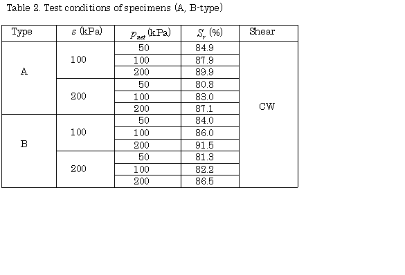
This specimen made from slurry was saturated (B-value greater than 0.95) and consolidated isotropically under 45 kPa in the triaxial cell. After measuring the size of specimen, the specimen was reconsolidated isotropically under a certain confining pressure pc'. Next, the pore water in the specimen was drained through the ceramic disk under a constant p-ua (= pc' ) by applying a certain ua from the top of the specimen. This stress history is shown schematically in Fig. 7. In this dehydration process, though water was drained for a long time, the dehydration process was terminated after 3000 minutes. This is because the drained volume of water per unit time became very small and the equilibrium state was achieved at that time (Fig. 8). The time history of the drained volume of water and the distribution of water content in the specimen after dehydration are shown in Figs. 8 and 9, respectively. It is clear that the drained volume of water became very small after 3000 minutes and the difference in water content in the specimen was less than 0.5%. Triaxial compression tests, with constant lateral stress σr, were carried out under constant water content (CW) condition (the pore air was allowed to drain while the pore water was undrained). The rate of strain was controlled until the failure of the specimen. The test conditions of the specimen are summarized in Table 2.

2. B-type specimen
This specimen made from slurry was saturated (B-value greater than 0.95) and consolidated isotropically under 45kPa in the triaxial cell. After measuring the size of the specimen, the specimen was drained through the ceramic disk under a constant net pressure p-ua (= 45kPa) with the application of a certain pore air pressure ua from the top of the specimen. After dehydration for 3000 minutes, the specimen was reconsolidated isotropically under a certain net pressure ( p-ua ). The reconsolidation time was set at 180 minutes by the application of the 3t method (Kamei et al., 1987; Oda et al., 1989). This stress history is also shown in Fig. 7. Triaxial compression tests were carryied out on the specimen created as mentioned above. The method of triaxial compression tests for the B-type specimen was the same as that for the A-type specimen. The test conditions of this specimen are also summarized in Table 2.
3. C-type specimen
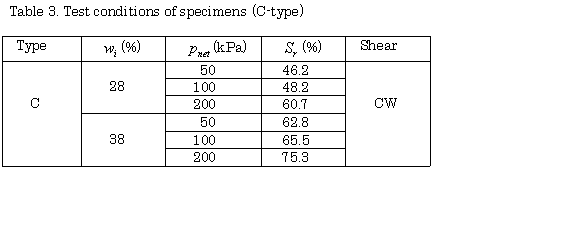
The C-type specimen was made by depositing moist soil with a certain water content. This deposit was very loose because it had already undergone the effect of suction. The suction should be changed for statically one-dimensional compression. The statically compacted specimen was consolidated isotropically under 45kPa in the triaxial cell. After measuring its size, the specimen was drained through the ceramic disk under a constant p-ua (= 45kPa) by applying a certain ua (= 100kPa) from the top of the specimen. In this process, water was drained because the water content was larger than that of the steady state in which a target matric suction was applied. After dehydration for 1000 minutes, the specimen was reconsolidated isotropically under a certain net pressure ( p-ua ). The 3t method defined the reconsolidation time as 2000 minutes for the C-type specimen. The stress history of the C-type specimen is not as clear as those of the A and B-type specimens made from slurry. Though the final condition is the same for the A, B and C-type specimens, densities are different because of the effect of stress history. Triaxial compression tests were carried out on the C-type specimen using the same method as that for the A-type or B-type specimens. The test conditions of the specimen are summarized in Table 3.

Torsional Shear Test Procedure
Torsional shear tests were performed on specimens made from the same method as for the A-type specimen in the triaxial test using two different shear conditions, i.e., constant water content (CW) and constant suction (CS) test. Though matric suction varied during shear in the CW test, it was constant during shear in the CS test. The shear strain rates are 0.015%/min and 0.005%/min in the CW and CS tests, respectively.
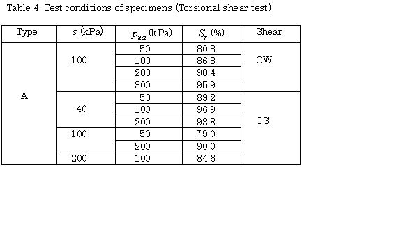
The specimen made from slurry was saturated (B-value greater than 0.95) and consolidated isotropically under 45kPa in the triaxial cell. After measuring the size of the specimen, it was isotropically reconsolidated under a certain confining pressure pc'. Next, the specimen was drained through the ceramic disk for 3000 minutes under a constant p-ua (= pc' ) by applying a certain ua from the top of the specimen. Torsional shear tests, under a constant pnet, α=45o and b = 0.5, were carried out under constant water content and drained condition with strain control until the failure of the specimen. In the above, α is the direction of the major principal stress relative to the vertical axis. The test conditions of the specimen are summarized in Table 4.

Stress and Strain Parameters
The idealized stress condition in a hollow cylindrical element is illustrated in Fig. 10. The average values of the four stresses and four strains, namely, vertical stress σz, radial stress σr, circumferential stress σθ, shear stress σzθ, axial strain εz, radial strain εr, circumferential strain εθ and shear strain γzθ = 2σzθ are calculated using the expressions given by Hight et al. (1983). The correction for the membrane forces proposed by Tatsuoka et al. (1986) was introduced in this research. The stress and strain parameters used in this research are defined as follows.
Matric suction, s :

where ua and uw are pore air and water pressure, respectively.
Net mean stress, pnet :

For the saturated specimen, the effective mean stress p' is adopted instead of net mean stress pnet.
Deviator stress, q :

Direction of the major principal stress relative to the vertical axis, α :

Relative magnitude of the intermediate principal stress, b :

Volumetric strain, εv :

Shear (Deviator) strain, εs :

RETURN